Cyclone separator
Cyclone separator
The cyclone separator is designed and manufactured in compliance with the requirements of GB/T 150 Pressure Vessels and TSG 21 Safety Technical Supervision Regulation for Stationary Pressure Vessels.
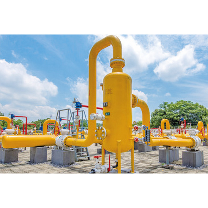
Natural gas enters the cyclone separation zone through the equipment inlet. When the gas containing impurities enters the cyclone component axially, the airflow is strongly rotated by the guiding effect of the guide vanes, spiraling downward along the cylinder into the cyclone body. Large-density liquid droplets and dust particles are thrown toward the cylinder wall by centrifugal force and, under gravity, flow downward along the cylinder wall to the dust outlet of the cyclone tube, reaching the liquid storage area at the bottom of the equipment, and finally exiting through the bottom outlet.
The rotating airflow contracts toward the center of the cylinder, forming a secondary vortex that flows upward through the guide tube into the purified natural gas chamber, then exits through the top outlet of the equipment.
Structural Characteristics
-
Designed for higher medium flow rates with minimal pressure loss, the multi-tube cyclone bundle effectively separates impurities from the medium simultaneously.01
-
The compact rotational diameter within cyclone tubes ensures a robust centrifugal force field even at low flow rates and velocities, guaranteeing optimal separation efficiency.02
-
Smooth medium flow with low pressure drop (<0.05MPa under normal operation).03
-
An integrated dust accumulation chamber enhances dirt-holding capacity, extends maintenance intervals, and reduces operational costs.04
-
Positioned below the main cylinder and outside the airflow path, the chamber eliminates re-entrainment for improved efficiency.05
-
The cyclone tube bundle requires no disassembly for cleaning, offering maintenance-free operation throughout its service life.06
-
Optional accessories: Differential pressure gauge, switch, or transmitter07
-
Optional accessories: Level gauge, switch, or transmitter08
-
Optional accessories: Pressure gauge or transmitter09
-
Optional accessories: Safety valve, blowdown valve, and automatic drainage system10
-
Optional accessories: Quick-opening blind flange for handholes11
Main Technical Parameters
| Working medium | Low-sulfur natural gas, manufactured gas, liquefied petroleum gas, and other non-corrosive gases |
| Design temperature | -19℃~ 60℃、-39℃~ 60℃ |
| Design pressure | 1.6MPa、2.5MPa、4.0MPa、6.3MPa、10MPa |
| Cylinder size | DN300 ~ DN1200 |
| Connection size | DN150 ~ DN600 |
| Filtration efficiency | ≥ 99%(for solid particles ≥10μm) |
| Filtration accuracy | 5μm、10μm、20μm |
| Main pressure-bearing component materials | Q345R、Q345D、16Mn |
Product Recommendation